Almost all UOS, all products of radio electronics and electrical engineering manufactured by industrial organizations and enterprises, home craftsmen, young technicians and radio amateurs, contain a certain amount of various purchased ERI and elements produced mainly by the domestic industry. But lately there has been a tendency to use ERE and foreign-made components. These include, first of all, PPP, capacitors, resistors, transformers, chokes, electrical connectors, batteries, HIT, switches, installation products and some other types of ERE.
Used purchased components or independently manufactured ERE are necessarily reflected in the circuit diagrams and wiring diagrams of devices, in drawings and other TD, which are carried out in accordance with the requirements of ESKD standards.
Particular attention is paid to circuit diagrams, which determine not only the main electrical parameters, but also all the elements included in the device and the electrical connections between them. To understand and read electrical circuit diagrams, you must carefully familiarize yourself with the elements and components included in them, know exactly the scope and principle of operation of the device in question. As a rule, information about the applied ERE is indicated in reference books and specifications - a list of these elements.
The connection of the list of ERE components with their conditional graphic designations is carried out through reference designations.
To construct conventional graphic symbols for ERE, standardized geometric symbols are used, each of which is used separately or in combination with others. At the same time, the meaning of each geometric image in the symbol in many cases depends on the combination with which other geometric symbol it is used.
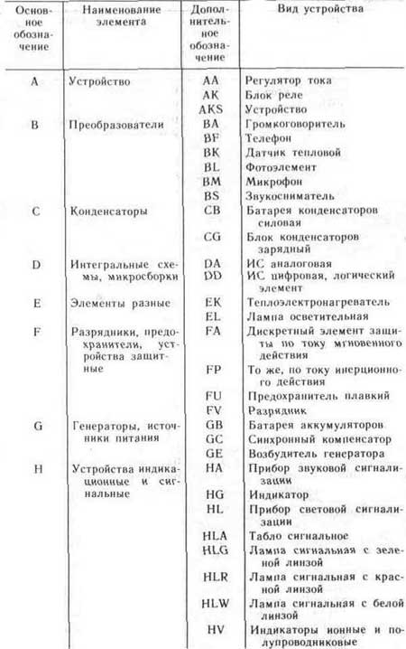
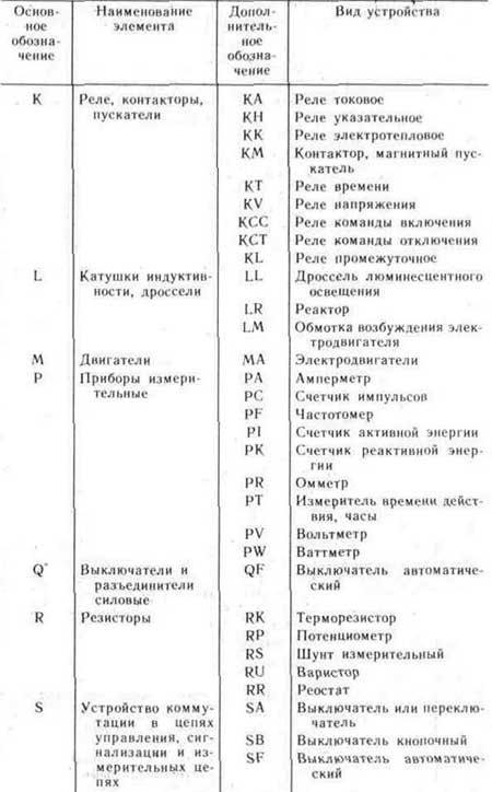
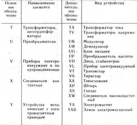
The standardized and most commonly used ERE graphic symbols in circuit diagrams are shown in Fig.1. These designations apply to all components of circuits, including ERE, conductors and connections between them. And here, the condition for the correct designation of the same type of ERE components and products is of paramount importance. For this purpose, positional designations are used, the mandatory part of which is the letter designation of the type of element, the type of its construction and the digital designation of the ERE number. The diagrams also use an additional part of the designation of the ERE position, indicating the function of the element, in the form of a letter. The main types of letter designations of circuit elements are given in Table 1.
The designations on the drawings and diagrams of elements of general use refer to qualification ones, establishing the type of current and voltage, the type of connection, the methods of regulation, the shape of the pulse, the type of modulation, electrical connections, the direction of transmission of current, signal, energy flow, etc.
At present, the population and the trade network use a significant number of various electronic devices and devices, radio and television equipment, which are manufactured by foreign firms and various joint-stock companies. In stores, you can purchase various types of ERI and ERE with foreign designations. In table. 1. 2 provides information on the most common ERE in foreign countries with the appropriate designations and their analogues of domestic production.
This information is published for the first time in such volume.
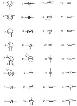
1- transistor structure p-n-p in the case, general designation;
2- transistor structure p-p-p in the case, general designation,
3 - field effect transistor with pn junction and n channel,
4 - field effect transistor with p-n junction and p channel,
5 - unijunction transistor with an n-type base, b1, b2 - base terminals, e - emitter terminal,
6 - photodiode,
7 - rectifier diode,
8 - zener diode (avalanche rectifier diode) one-sided,
9 - thermal-electric diode,
10 - diode thyristor, erasable in the opposite direction;
11 - zener diode (diodolavin rectifier) with double-sided
conductivity,
12 - triode thyristor.
13 - photoresistor,
14 - variable resistor, rheostat, general designation,
15 - variable resistor,
16 - variable resistor with taps,
17 - construction resistor-potentiometer;
18 - thermistor with a positive temperature coefficient of direct heating (heating),
19 - varistor,
20 - fixed capacitor, general designation,
21 - polarized capacitor of constant capacitance;
22 - oxide polarized electrolytic capacitor, general designation;
23 - constant resistor, general designation;
24 - constant resistor with a rated power of 0.05 W;
25 - constant resistor with a rated power of 0.125 W,
26 - constant resistor with a rated power of 0.25 W,
27 - constant resistor with a rated power of 0.5 W,
28 - constant resistor with a rated power of 1 W,
29 - constant resistor with a rated power dissipation of 2 W,
30 - constant resistor with a rated power dissipation of 5 W;
31 - constant resistor with one symmetrical additional tap;
32 - constant resistor with one asymmetrical additional tap;
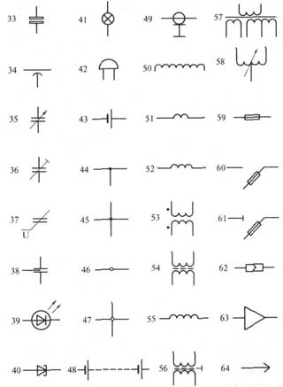
Conventional graphic symbols of ERE in electrical, radio engineering and automation circuits
33 - non-polarized oxide capacitor,
34 - pass-through capacitor (arc denotes body, external electrode),
35 - capacitor of variable capacity (the arrow indicates the rotor);
36 - tuning capacitor, general designation
37 - varicap.
38 - noise suppression capacitor;
39 - LED,
40 - tunnel diode;
41 - incandescent lighting and signal lamp
42 - electric bell
43 - galvanic or battery cell;
44 - electrical communication line with one branch;
45 - electrical communication line with two branches;
46 - a group of wires connected to one electrical connection point. two wires;
47 - four wires connected to one electrical connection point;
48 - a battery of galvanic cells or a battery;
49 - coaxial cable. The screen is connected to the body;
50 - winding of a transformer, autotransformer, inductor, magnetic amplifier;
51 - working winding of the magnetic amplifier;
52 - control winding of the magnetic amplifier;
53 - a transformer without a core (magnetic circuit) with a constant connection (dots indicate the beginning of the windings);
54 - transformer with a magnetodielectric core;
55 - inductor, choke without magnetic circuit;
56 - single-phase transformer with a ferromagnetic core and a screen between the windings;
57 - single-phase three-winding transformer with a ferromagnetic magnetic circuit with a tap in the secondary winding;
58 - single-phase autotransformer with voltage regulation;
59 - fuse;
60 - fuse switch;
b1 - fuse-disconnector;
62 - connection pin detachable;
63 - amplifier (the direction of signal transmission is indicated by the top of the triangle on the horizontal communication line);
64 - pin of detachable contact connection;
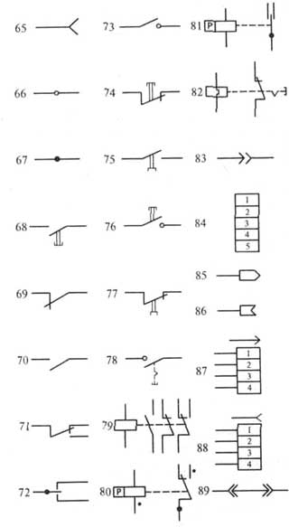
Conventional graphic symbols of ERE in electrical, radio engineering and automation circuits
65 - socket for detachable contact connection,
66 - collapsible connection contact, for example, using a clamp
67 - contact of a non-separable connection, for example, carried out by soldering
68 - single-pole push-button switch with NO contact
self-return
69 - switching device opening contact, general designation
70 - contact of the switching device (switch, relay) closing, general designation. The switch is single-pole.
71 - switching device contact, general designation. Single pole two way switch.
72 - three-position switching contact with neutral position
73 - closing contact without self-return
74 - push-button switch with break contact
75 - push-button exhaust switch with closing contact
76 - push-button switch with button return,
77 - push-button exhaust switch with NC contact
78 - push-button switch with return by pressing the button again,
79 - electrical relay with make, break and changeover contacts,
80 - relay polarized in one direction of current in the winding with a neutral position
81 - relay polarized in both directions of current in a winding with a neutral position
82 - electrothermal relay without self-return, with return by pressing the button again,
83- plug single-pole connection
84 - socket for a five-wire plug-in connection,
85 pin connector coaxial connection
86 - contact socket
87 - four-wire connection pin,
88 four-wire socket
89 - jumper switching opening circuit
Symbols of circuit elements
Standard conditional graphic and letter designations of elements of electrical circuits
| E | EMF source | |
| R | Resistor, active resistance | |
| L | Inductance, coil | |
| C | capacitance, capacitor | |
| G | Alternator, feed circuit | |
| M | AC motor | |
| T | Transformer | |
| Q | Power switch (for voltage over 1kV) | |
| QW | Load break switch | |
| QS | Disconnector | |
| F | Fuse | |
| Busbars with connections | ||
| Detachable connection | ||
| QA | Automatic switch for voltage up to 1 kV | |
| KM | Contactor, magnetic starter | |
| S | knife switch | |
| TA | Current transformer | |
| TA | Zero sequence current transformer | |
| TV | Three-phase or three single-phase voltage transformers | |
| F | Discharger | |
| TO | Relay | |
| KA, KV, KT, KL | Relay winding | |
| KA, KV, KT, KL | NO relay contact | |
| KA, KV, KT, KL | Relay opening contact | |
| CT | Timing relay contact | |
| CT | Time relay contact closing with return delay | |
| Measuring instrument | ||
| measuring instrument | ||
| Ammeter | ||
| Voltmeter | ||
| Wattmeter | ||
| Varmeter |
Site materials used.