No person, no matter how talented and savvy, can learn to understand electrical drawings without first becoming familiar with the conventions that are used in electrical installation at almost every step. Experienced specialists argue that only an electrician who has thoroughly studied and mastered all the generally accepted designations used in project documentation can have a chance to become a true professional in their field.
Greetings to all friends on the Electrician in the House website. Today I would like to pay attention to one of the initial issues that all electricians face before installation - this is the design documentation of the facility.
Someone makes it himself, someone provides the customer. Among the many of this documentation, you can find instances in which there are differences between symbols certain elements. For example, in different projects, the same switching device can be graphically displayed in different ways. Has this happened?
It is clear that it is impossible to discuss the designation of all elements within one article, so the topic of this lesson will be narrowed down, and today we will discuss and consider how it is performed.
Each novice master is obliged to carefully read the generally accepted GOSTs and the rules for marking electrical elements and equipment on plan diagrams and drawings. Many users may disagree with me, arguing that why do I need to know GOST, I just install sockets and switches in apartments. Schemes must be known to design engineers and professors at universities.
I assure you it is not. Any self-respecting specialist must not only understand and be able to read electrical circuits, but also must know how various communication devices, protective devices, metering devices, sockets and switches are graphically displayed on the diagrams. In general, actively apply project documentation in their daily work.
Ouzo designation on a single-line diagram
The main RCD designation groups (graphic and alphabetic) are used by electricians very often. The work on drawing up work schemes, schedules and plans requires very great care and accuracy, since a single inaccurate indication or mark can lead to a serious error in further work and cause the failure of expensive equipment.
In addition, incorrect data can mislead third-party specialists involved in electrical installation and cause difficulties in the installation of electrical communications.
Currently, any ouzo designation on the diagram can be represented in two ways: graphic and alphabetic.
What legal documents should be referred to?
Of the main documents for electrical circuits that refer to the graphic and letter designation of switching devices, the following can be distinguished:
- - GOST 2.755-87 ESKD "Conditional graphic designations in electrical circuits of switching devices and contact connections";
- - GOST 2.710-81 ESKD "Alphanumeric designations in electrical circuits".
Graphic designation of the RCD on the diagram
So, above, I presented the main documents according to which the designations in electrical circuits are regulated. What do these GOSTs give us to study our issue? I'm ashamed to admit it, but absolutely nothing. The fact is that today in these documents there is no information on how the ouzo designation should be performed on a single-line diagram.
Current GOST no special requirements for the rules for compiling and using RCD graphic symbols does not push. That is why some electricians prefer to use their own sets of values \u200b\u200band labels to label certain components and devices, each of which may differ slightly from the values \u200b\u200bfamiliar to our eyes.
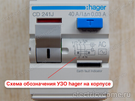
For example, let's look at what designations are applied to the case of the devices themselves. Residual current device from hager:
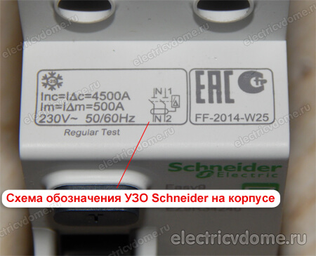
Or, for example, an RCD from Schneider Electric:
To avoid confusion, I suggest that you jointly develop a universal version of the designation of the RCD, which can be used as a guide in almost any working situation.
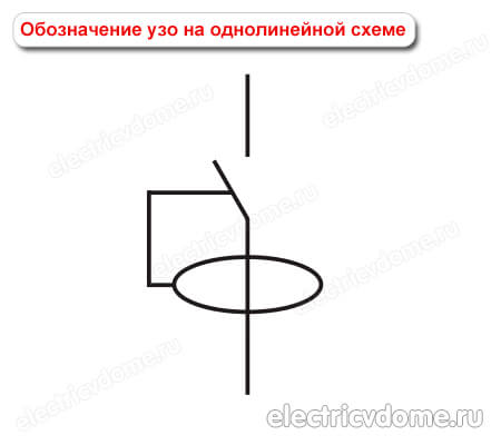
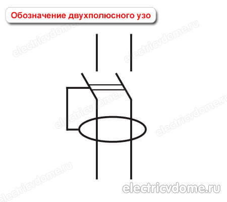
According to its functional purpose, a residual current device can be described as follows - it is a switch that, during normal operation, is able to turn on / off its contacts and automatically open the contacts when a leakage current appears. Leakage current is a differential current that occurs when the electrical installation is not operating normally. Which organ responds to differential current? A special sensor is a zero-sequence current transformer.
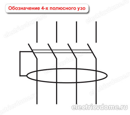
If we represent all of the above in graphical form, then it turns out that RCD symbol on the diagram can be represented as two secondary designations - a switch and a sensor that reacts to differential current (zero sequence current transformer) that acts on the contact disconnection mechanism.
In this case graphic designation of ouzo on a single-line diagram will look like this.
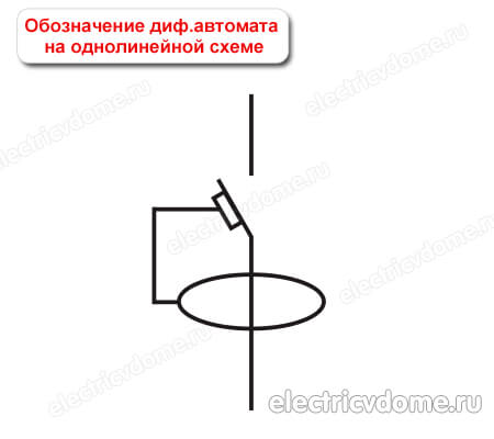
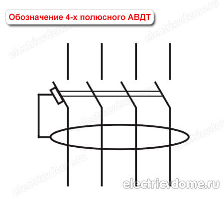
How is the difavtomat indicated on the diagram?
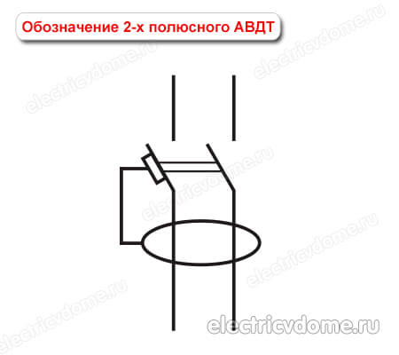
About designations of difavtomatov in GOST no data available at the moment. But, based on the above scheme, the difavtomat can also be graphically represented in the form of two elements - an RCD and a circuit breaker. In this case, the graphic designation of the difavtomat on the diagram will look like this.
The letter designation of ouzo on electrical diagrams
Any element on the electrical circuits is assigned not only a graphic designation, but also an alphabetic designation indicating the position number. Such a standard is regulated by GOST 2.710-81 "Alphanumeric designations in electrical circuits" and is mandatory for application to all elements in electrical circuits.
So, for example, according to GOST 2.710-81, circuit breakers are usually designated by a special alphanumeric designation in this way: QF1, QF2, QF3, etc. Breakers (disconnectors) are designated as QS1, QS2, QS3, etc. Fuses in the diagrams are designated as FU with the corresponding serial number.
Similarly, as with graphic symbols, there is no specific data in GOST 2.710-81 on how to perform alphanumeric designation of RCDs and differential automata on the diagrams.
How to be in that case? In this case, many masters use two designations.
The first option is to use the most convenient alphanumeric designation Q1 (for RCDs) and QF1 (for RCBOs), which indicate the functions of the switches and indicate the serial number of the device in the circuit.
That is, the encoding of the letter Q means - "switch or knife switch in power circuits", which may well be applicable to the designation of the RCD.
The code combination QF stands for Q - “switch or knife switch in power circuits”, F - “protective”, which may well be applicable not only to conventional machines, but also to differential machines.
The second option is to use the alphanumeric combination Q1D - for the RCD and the combination QF1D - for the differential machine. According to Appendix 2 of Table 1 of GOST 2.710, the functional meaning of the letter D means - " differentiating».
I very often met on real circuits such a designation QD1 - for residual current devices, QFD1 - for differential automata.
What conclusions can be drawn from the above?
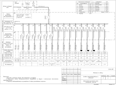
How ouzo is indicated on a single-line diagram - an example of a real project
As the well-known proverb says, “it is better to see once than hear a hundred times”, so let's look at a real example.
Suppose we have a single-line power supply scheme for an apartment in front of us. Of all these graphic designations, the following can be distinguished:
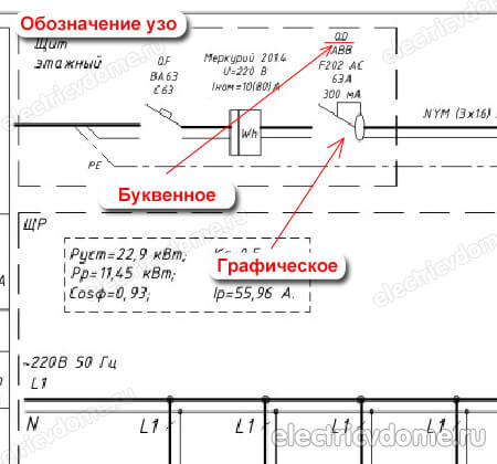
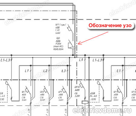
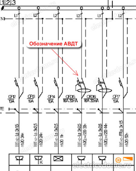
The introductory residual current device is located immediately after the meter. By the way, as you may have noticed, the letter designation of the RCD is QD. Another example of how ouzo is indicated:
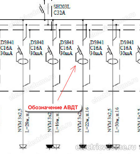
Note that in the diagram, in addition to the UGO elements, their marking is also applied, that is: the type of device by the type of current (A, AC), rated current, differential leakage current, number of poles. Next, we turn to the UGO and the marking of differential automata:
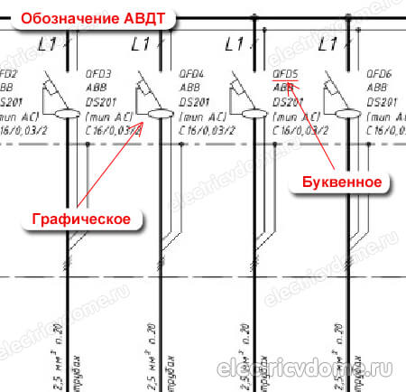
The outlet lines in the diagram are connected through differential machines. Letter designation difavtomat on the circuit QFD1, QFD2, QFD3, etc.
One more example how differential automata are indicated on a single-line diagram shop.
That's all dear friends. This concludes our lesson for today. I hope this article was useful for you and you found the answer to your question here. If you have any questions, ask them in the comments, I will be happy to answer. Let's share our experience, who designates the RCD and RCBO in the diagrams. I would be grateful for a repost in social networks))).