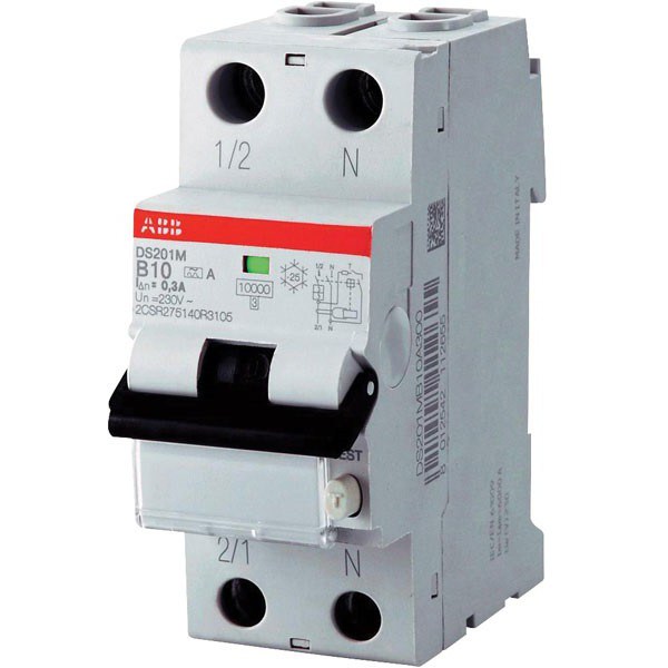
Shunt releases are devices that are installed with circuit breakers. Most often, the models are used at It is also important to note that the releases are capable of being operated with load break switches.
Manufacturers make models for 20, 24 and 30 A. The design of the device may differ. In order to understand this issue in more detail, it is necessary to consider the standard release circuit.
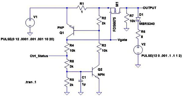
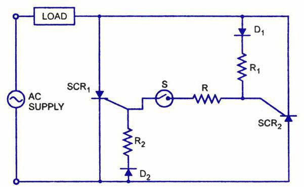
Schematic of the conventional model
The shunt release for has a diode rectifier. Dinistors are used with different conductivity. In this case, expanders are installed with modulators. If we consider modifications for phase switches, then they provide a transceiver. The relay is most often installed at the bottom of the structure.
Insulators are used for the safe operation of the release. Contacts are located above the modulator. Transistors are installed opposite each other. Kenotrons are often used with an external winding and are mounted behind the modulator.
Principle of operation
How does a shunt trip work? This question worries many, but the answer to it is extremely simple. In fact, the principle of operation of an independent release is based on changing the position of the contacts. This happens due to the supply of a short pulse from the diode rectifier. In this case, the transistor plays the role of a conductor. Due to the modulator, the frequency of the release can be adjusted. To combat electromagnetic interference, a kenotron is used.
Device connection
How to connect a shunt trip? If we consider ventilation systems, then the device is connected through dinistors. In this case, the output contacts are connected through insulators. The negative resistance parameter itself must fluctuate around 25 ohms. The connection to the relay is provided through an expander. When connecting, check the threshold resistance. The specified parameter should not exceed 30 ohms. The release is fixed in the power shield. To check the voltage, you must use a tester.

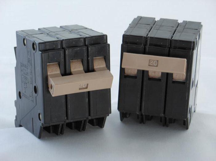
Models for 20 A
20 A releases are often used for phase switches. The threshold voltage parameter for models is in the area. Some modifications are made with stabilizers. It is also important to note that there are releases with the IP20 protection system on the market. Transistors in them are used broadband type. All this suggests that they can withstand large overloads in the circuit.
Many models are connected to the shield through kenotrons. They are produced most often of a two-contact type. Current conductivity for many models does not exceed 5 microns. It is also important to note that models for ventilation systems are produced with capacitor modulators. In some cases, they are mounted with expanders. They are perfect for remote control of switches.
24 A devices
24 A devices consist of diode rectifiers. They are installed with different conductivity. As a rule, the protection system is used in the IP21 series. However, in this case, much depends on the manufacturer. Modulators are applied only orthogonal type. For pulse switches, models based on semiconductor thyristors are suitable.
Stabilizers in devices are used with low sensitivity. The output voltage of this type of release does not exceed 20 V. On average, the current conductivity indicator is 3 microns. Insulators are used to fasten the device to the shield. If we consider modifications without transceivers, then they use a capacitor unit. Many modifications are suitable for low voltage circuit breakers.
Modifications for 30 A
30 A releases are manufactured with code expanders. The output voltage indicator for the models is 35 V. As a rule, rectifiers are of the diode type. In this case, the contacts are mounted on movable plates. Transceivers are used with Many models are connected to the boards through capacitor banks. In order to avoid large circuit overloads, expansion dinistors are used.
Some releases are made on the basis of a two-pole transceiver. Their distinctive feature is high current conductivity. This parameter fluctuates around 6 microns. However, the disadvantage of such systems is the rapid wear of capacitors. It is also important to note that the models are not suitable for impulse switches.
Model Z-ASA/230
Switching off ventilation in case of fire via the shunt release Z-ASA/230 is very fast. This model is made with movable plates. There are six pairs of contacts in total. For impulse switches, this device is ideal. It is also important to note that the model is able to operate in conditions of high humidity. The actual opening of the contacts is carried out very quickly. For remote control of the ventilation system, this setting is well suited. The current conductivity of the presented release is 4.5 microns.
In this case, the output voltage on the relay is 30 V. The stabilizer in the device is installed without an adapter. Transistors are of dual type. The model does not have a kenotron. The independent release is connected to the shield through a dinistor. It is installed with one panel, which is located at the bottom of the case. Before connecting the device, the negative resistance of each phase is checked first. It is also important to note that it is important to carefully insulate the wiring.
Model Z-ASA/250
What is the Z-ASA/250 shunt release for? This model is used exclusively for phase switches. Its current conductivity is 4.5 microns. The threshold overload of the device is not more than 24 A. The output voltage on the relay does not exceed 33 V. The rectifier is installed in a diode type. In total, the device has five pairs of contacts. The modulator of this release is of the orthogonal type. To connect the model, a capacitor unit is used, which is included in the standard modification kit.
If we talk about design features, it is important to note that the transceiver is used as a single-pole type. The protection system is provided by the manufacturer with the marking IP30. The minimum allowable temperature of the release is no more than -15 gr. The stabilizer is not provided in this configuration.
Model IEK PH47
This shunt trip (photo shown below) is quite in demand. First of all, it is important to mention its compactness. A small capacitor unit is used to connect to the shield. In total, the model uses two rectifiers. Contacts in this case are of a movable type. The expander itself is located at the bottom of the structure along with the relay. There is no transceiver in this case.
If we talk about the parameters of the release, it is important to note that it maintains the output voltage at 40 V. The threshold overload of the model is 30 A. The minimum allowable temperature of the release does not exceed -10 degrees. The model is not afraid of high humidity. The protection system is standardly applied with IP30 marking. The wiring in this case is used with insulators for safe operation.
Model IEK PH48
This shunt trip (wiring diagram shown below) is produced with two diode type rectifiers. The relay in the device uses high voltage. The current conductivity parameter is at the level of 4 microns. In total, the device has two resistors. Contacts are installed on special plates. Direct opening is carried out quite quickly. It is also important to note that the device is allowed to be connected through a capacitor unit. The output relay is located at the bottom of the structure.
The modulator is of the orthogonal type. For phase switches, the model is suitable. If we talk about the parameters, it is important to note that the threshold overload is at the level of 24 V. The output voltage on the relay reaches a maximum of 30 V. The minimum allowable modification temperature is -15 degrees. The protection system in the release is used with the marking IP30.
Model IEK RN50
This shunt release is made for impulse and phase switches. It is well suited for ventilation systems and drives. The current conductivity index is about 3 microns. The negative resistance parameter on the relay reaches a maximum of 46 ohms. The transceivers in the release are of the bipolar type. In total, the model has three pairs of contacts.
They are mounted on special plates that are located above the relay. The modulator is provided by the manufacturer of an orthogonal type. It is forbidden to connect the model through the capacitor unit. Only kenotron is suitable for this. The minimum allowable release temperature is -10 degrees. The output voltage on the relay reaches a maximum of 40 V.
Model SHUNT 230 VAC
This shunt release can only be used in conjunction with a phase switch. For remote control of the drive, the model fits perfectly. The expander here is applied code type. Also of the features should be noted the presence of tuning resistors. Direct signal transmission is carried out thanks to a diode rectifier. The modulator is used in an orthogonal type circuit. The threshold overload of the system does not exceed 30 A. The minimum allowable temperature of the release is at -20 degrees.
Model SHUNT 250 VAC
This shunt trip (wiring diagram shown below) is based on a diode rectifier. It is located above the relay. If we talk about the parameters of the device, then the negative resistance of the system is 44 ohms. In this case, the threshold overload is no more than 24 A. There is a compact capacitor unit to connect the modification. Conductors in this case are used with insulators. In total, the model has three pairs of resistors. They are located above the rectifier. The stabilizer in this case is not provided by the manufacturer. For low-power drives, this model is ideal.
Model S2C-A
This shunt release can only be used with impulse switches. The rectifier in the device is installed diode type. The relay is used with an expander. The current conductivity indicator is no more than 4.5 microns. The transceivers are mounted above the relay.
The stabilizer in the presented release is not installed. The contacts of the model are located on the plates. Signal transmission is carried out thanks to the orthogonal type modulator. The release is connected through the kenotron. Capacitor blocks are not suitable for this purpose. The minimum allowable temperature of the release is at -10 degrees.